|
|
WAVES ARE BEING MADE DOWN SOUTH AT THE CAPE OF STORMS MONOHULL SAILING WILL NEVER BE THE SAME AGAIN... |
|
|
WAVES ARE BEING MADE DOWN SOUTH AT THE CAPE OF STORMS MONOHULL SAILING WILL NEVER BE THE SAME AGAIN... |
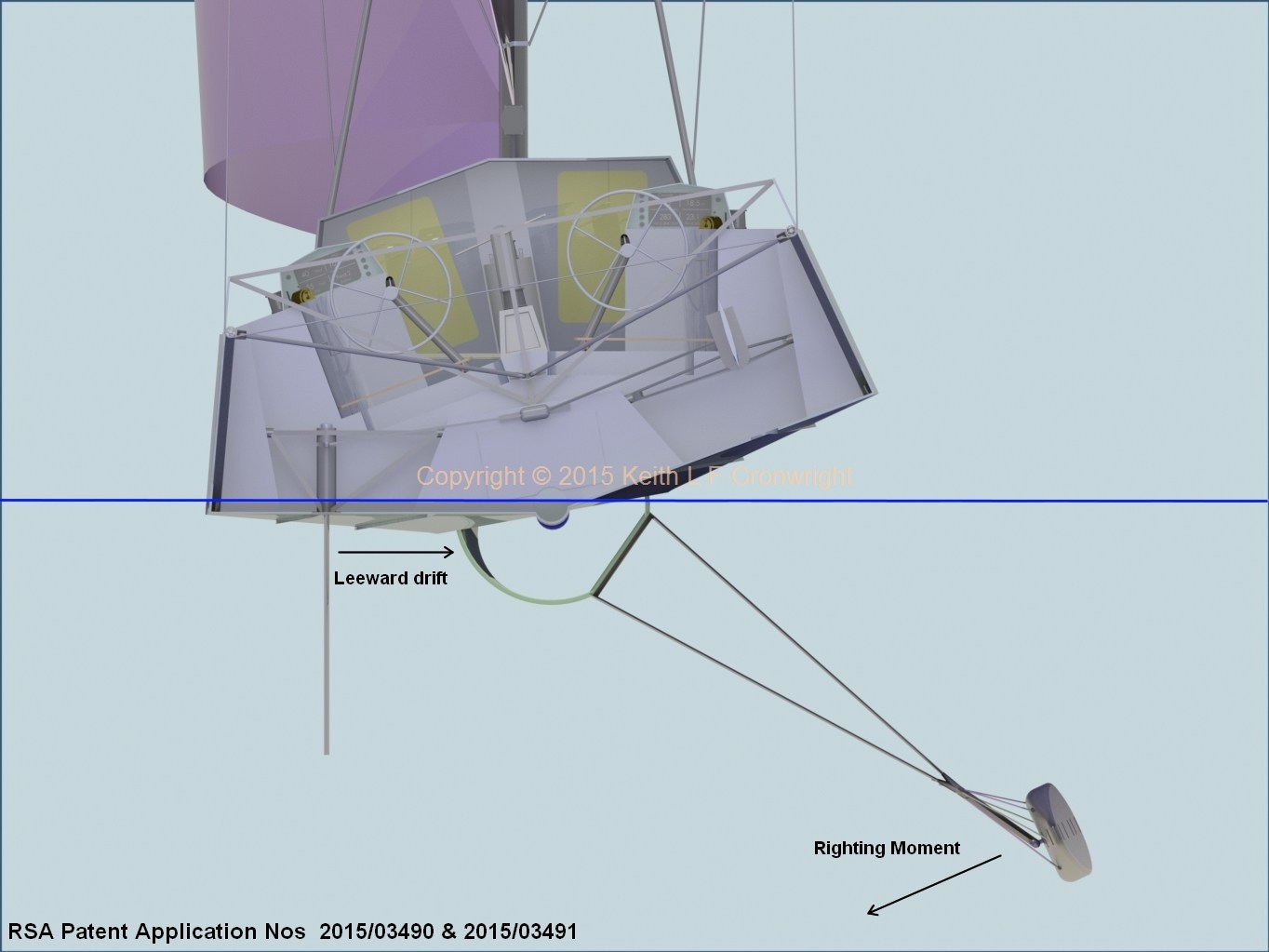
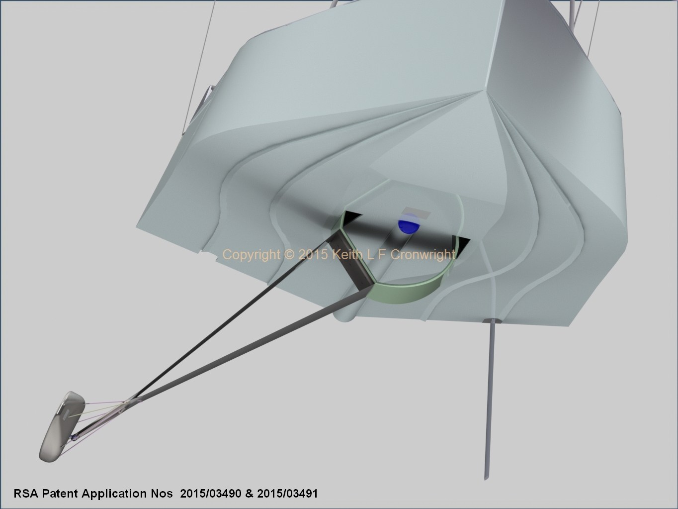
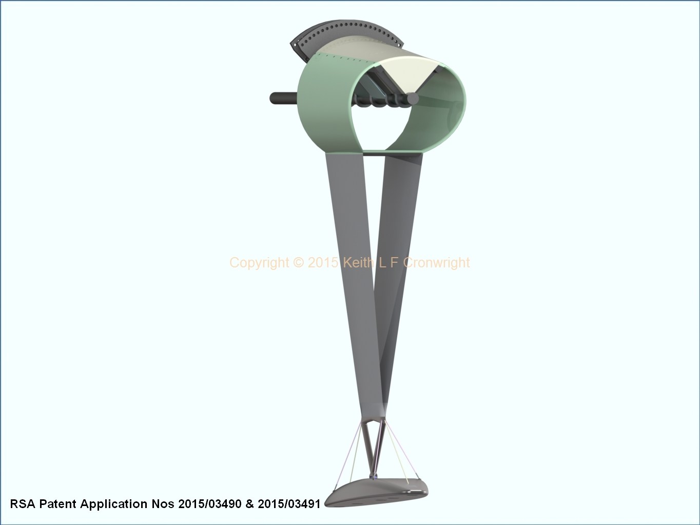
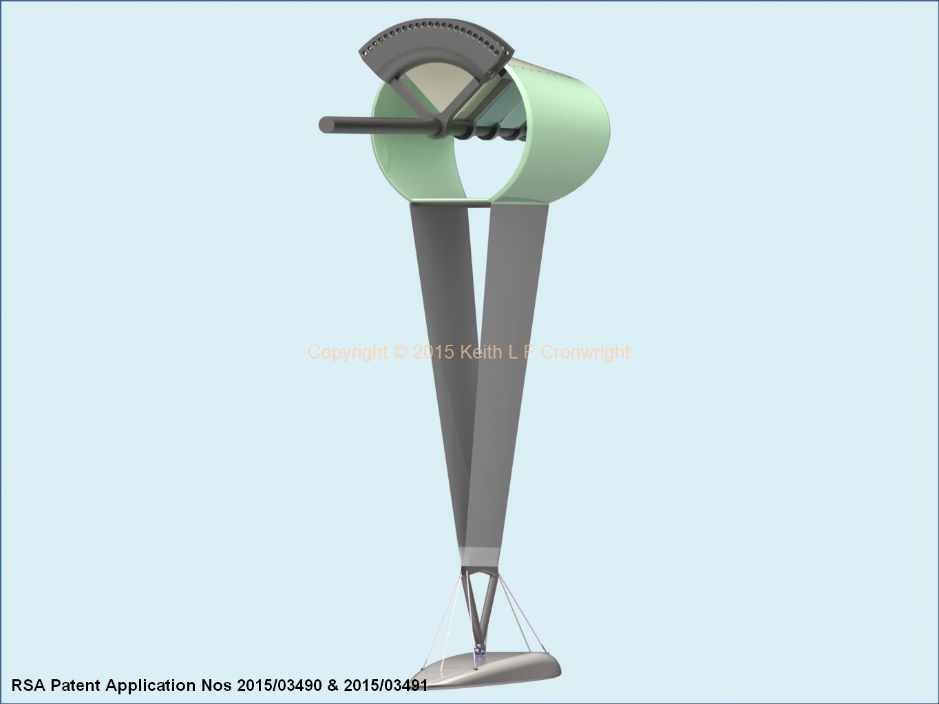
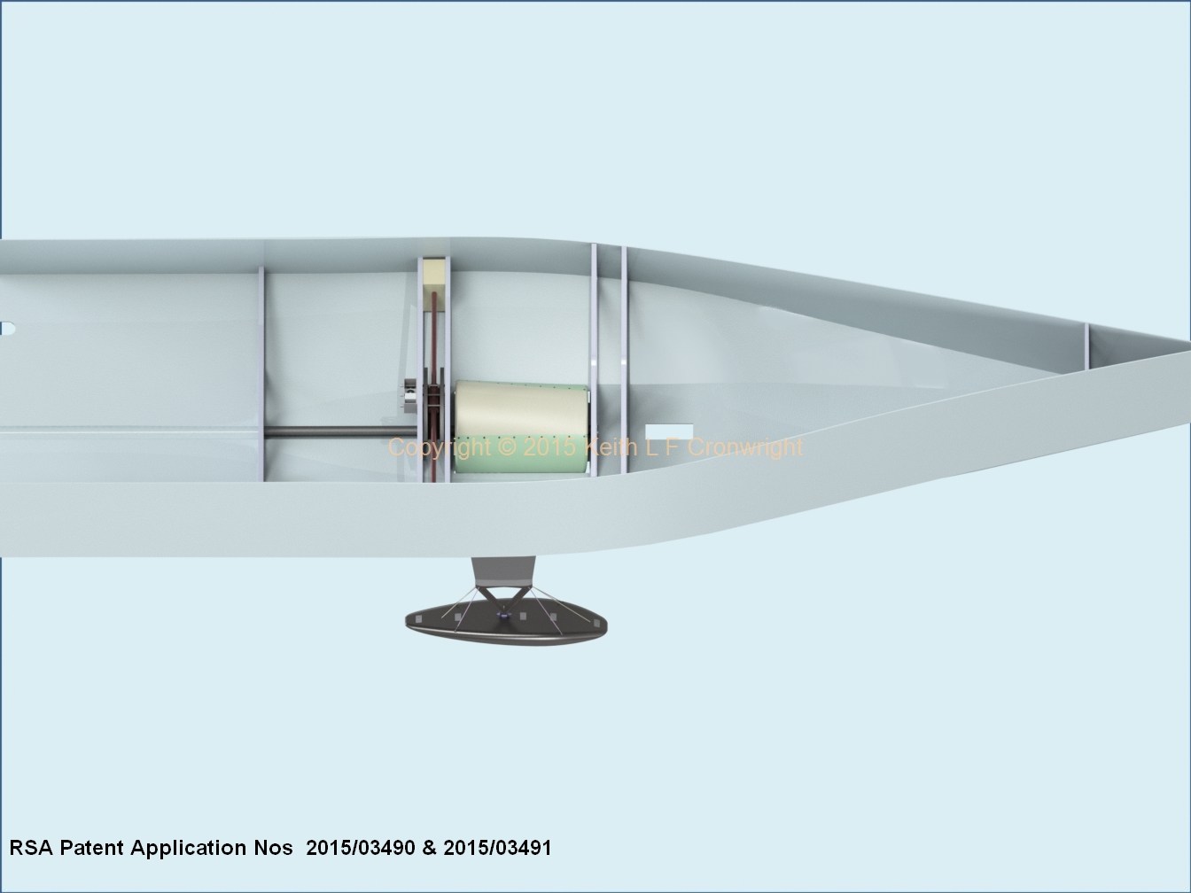
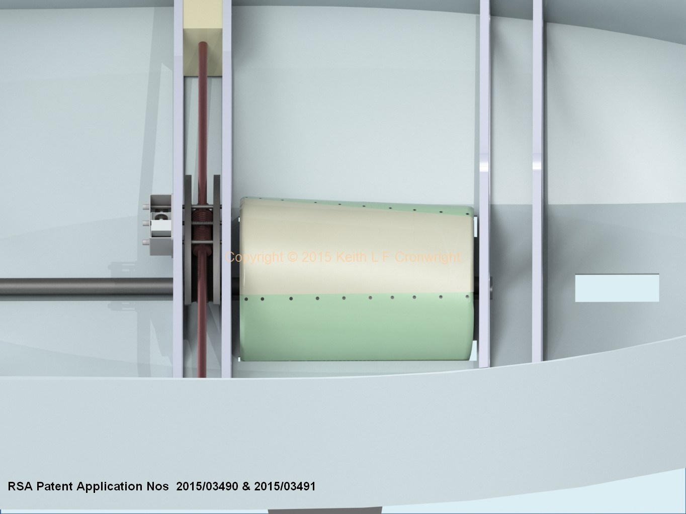
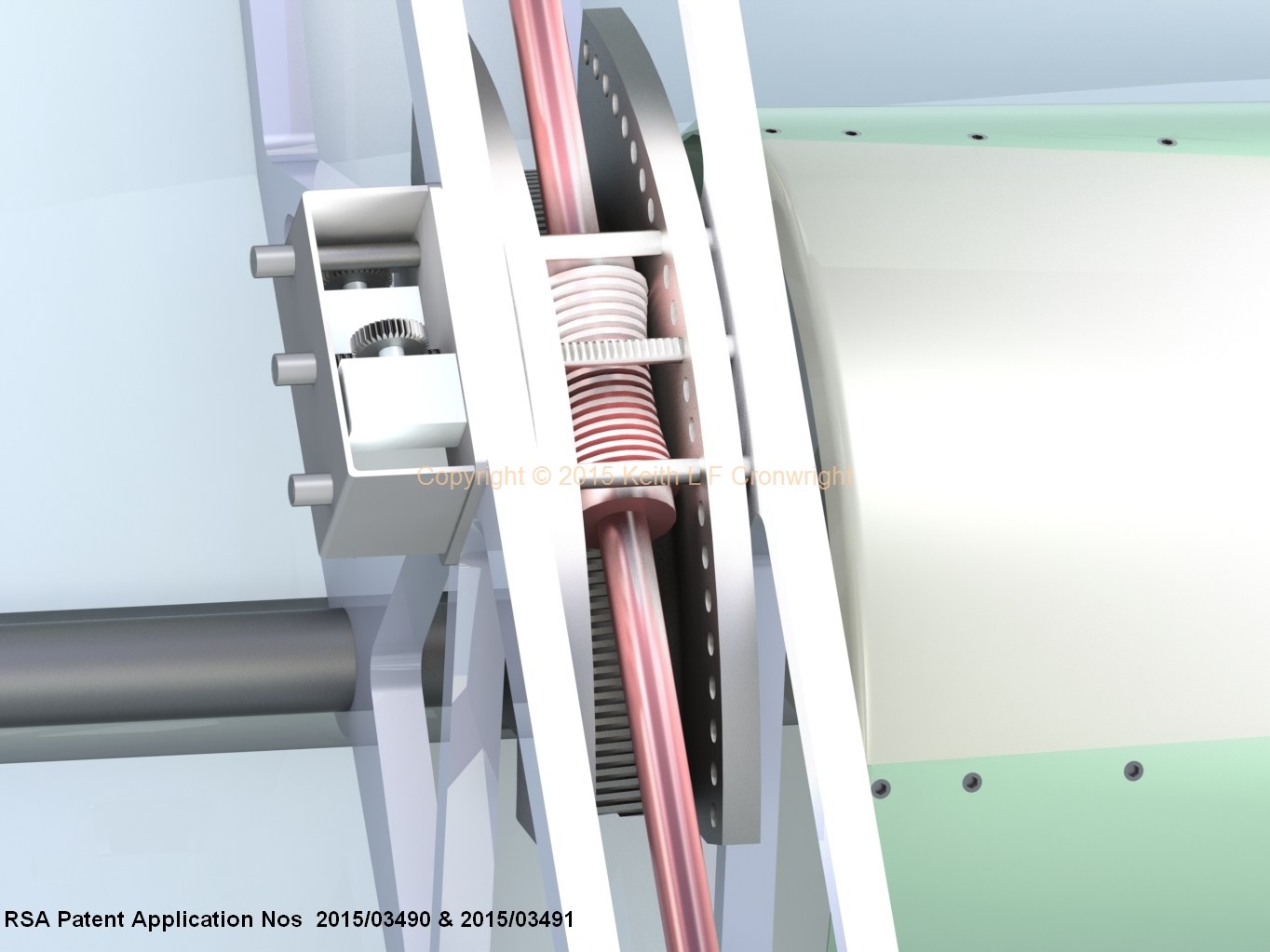
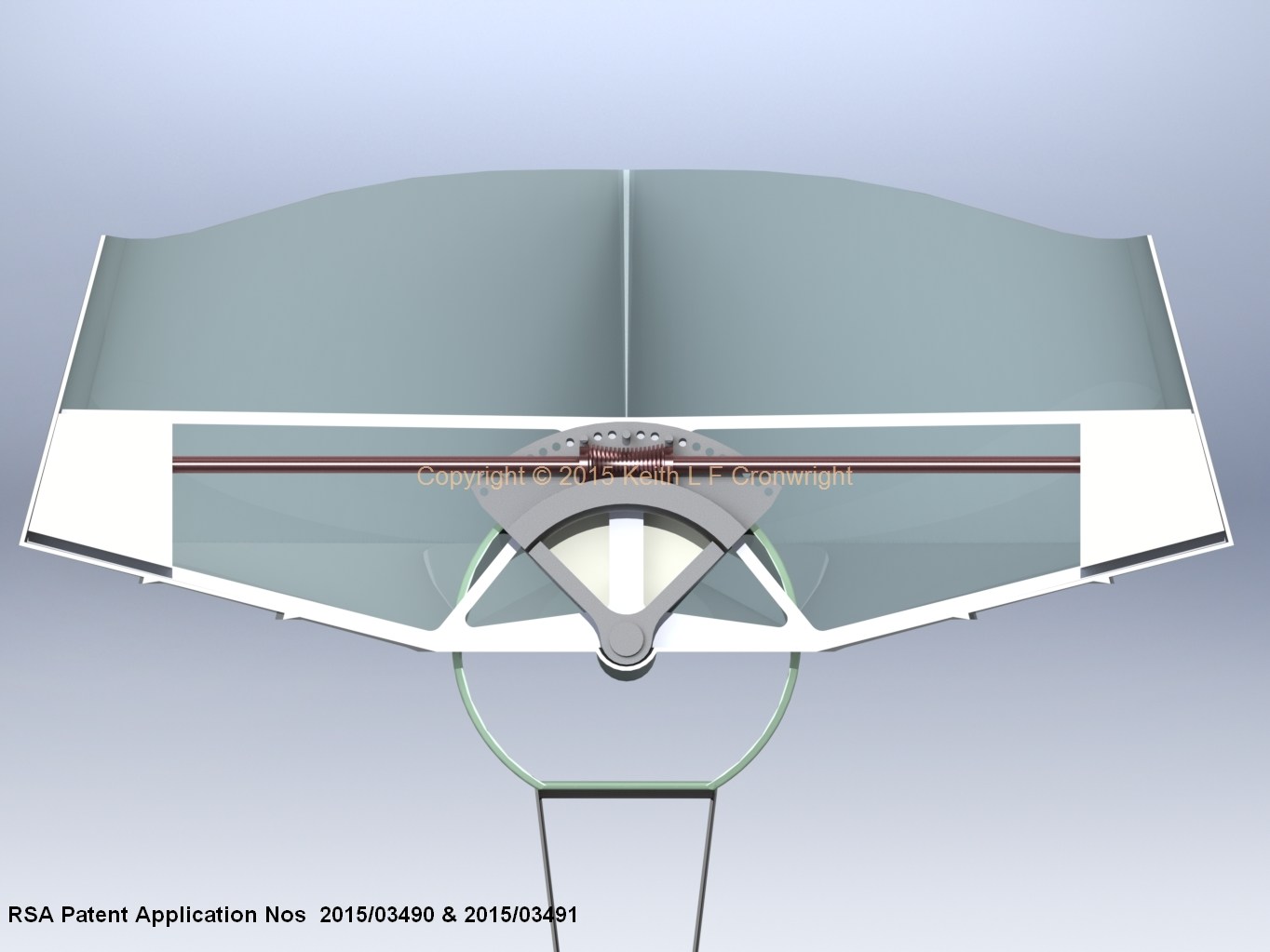
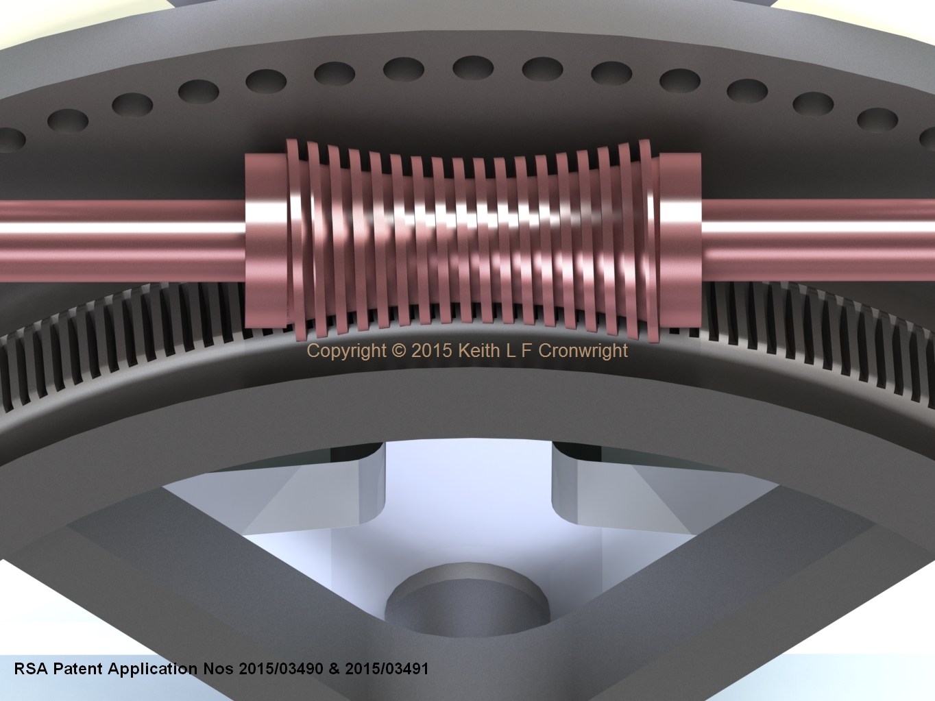
Mechanical Canting KeelWikipedia informs that in 1981 a canting keel system was first patented. During the 90s a further patent (by CBTF Technologies) of their hydraulic canting keel system was granted. Increasingly during the 21st century, racing boat specifications specified a hydraulic canting keel system. Hydraulic powered systems were however not without technical problems. Reports began appearing on the web of failure of hydraulics and fracturing/cracking of the hull-keel interfaces. In essence - keels were falling off!A constant source of energy is required to both reposition and maintain the hydraulically powered canting keel in its fixed position. Mechanical canting keel utilising actuators addresses the above problems. Keel is canted utilising a worm-gear actuator which is inherently 'self-locking'. Plainly stated - once the keel is relocated to a new position, it stays there - no energy is required to maintain a given attitude. Design of mechanical canting keel which includes a longitudinal shaft which articulates with multiple bulkheads and the canting mechanism, reduces the risk of structural failures so often seen with the hydraulic canting systems. This longitudinal shaft, by articulating with the multiple bulkheads and the canting mechanism, imparts a longitudinal 'stiffness' to the hull wherein canting mechanism and hull become 'one'. Design incorporates a second 'back-up' locking mechanism wherein locking pins absorb the energy associated with pounding thereby reducing the wear-and-tear of the worm-gear. Design facilitates the easily demounting of keel apparatus from hull. Ease of disassembly permits a stowage of a 40' 'canter' and keel in a 40' shipping container. The notion then of transporting a fleet of 40' 'canters' from one venue to the next, participating in a World 40' Maximo Offshore/Inshore Series is exciting. Imagine the road-show 'circus' commences racing in Newport then translocates across the Atlantic to Istanbul, the next leg being through the Suez Canal in Oman whereupon the 'fleet' of containers is shipped either south to Cape Town or New Zealand... TO ENLARGE IMAGE(S) PLEASE CLICK
|
Browse Menu ▼
|
|||||||||||||||||||||||||||||||||||||||||||||||
|
CONTACT |
|
|
The developments described are the subject of South African Patent Numbers 2015/03490 & 2015/03491
Adjustable Ballast Bulb for a Sailing Vessel - Patent Reference No. USA - US 10,322,773 B2 / Belgium, Denmark, France, United Kingdom, Ireland, Netherlands, Norway, Sweden - EP3297905 / Germany - 60 2016 037 150.2 / Italy - 502020000080611 Sailing Vessel - Patent Reference No. US 10,710,685 B2 Sailing Vessel - PCT (Patent Cooperation Treaty) WO 2016/185356 Australian Patent Ballast Bulb Granted - View Here South African Patent Ballast Bulb Granted - View Here All text, images, content, media and other information are © Copyright 2015. No unauthorised copying or reproduction is permitted. |
|